
Machine Design
Design, build, and test a powered mechanism that will automatically press arcade buttons on the playing field as rapidly as possible.
It used a DC electric motor and a closed loop position control system to move the button pressing mechanism to the desired position and orientation accurately enough to press the buttons and quickly enough to press as many as possible in 1 minute.
The design also had to be within a max volume, budget, and transmission angle deviation.
Team 11: Claudio Solano, Hayden Flowers, Olivia Gilbert, Julie Jarboe, Christian Yupanqui
MECE 3409 (Fall 2024)
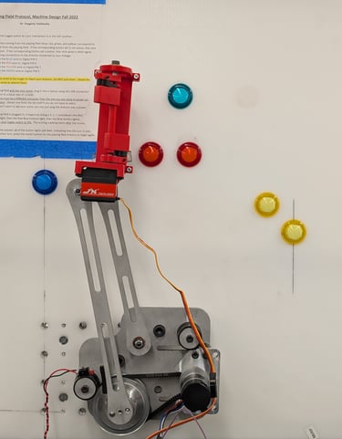
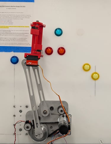
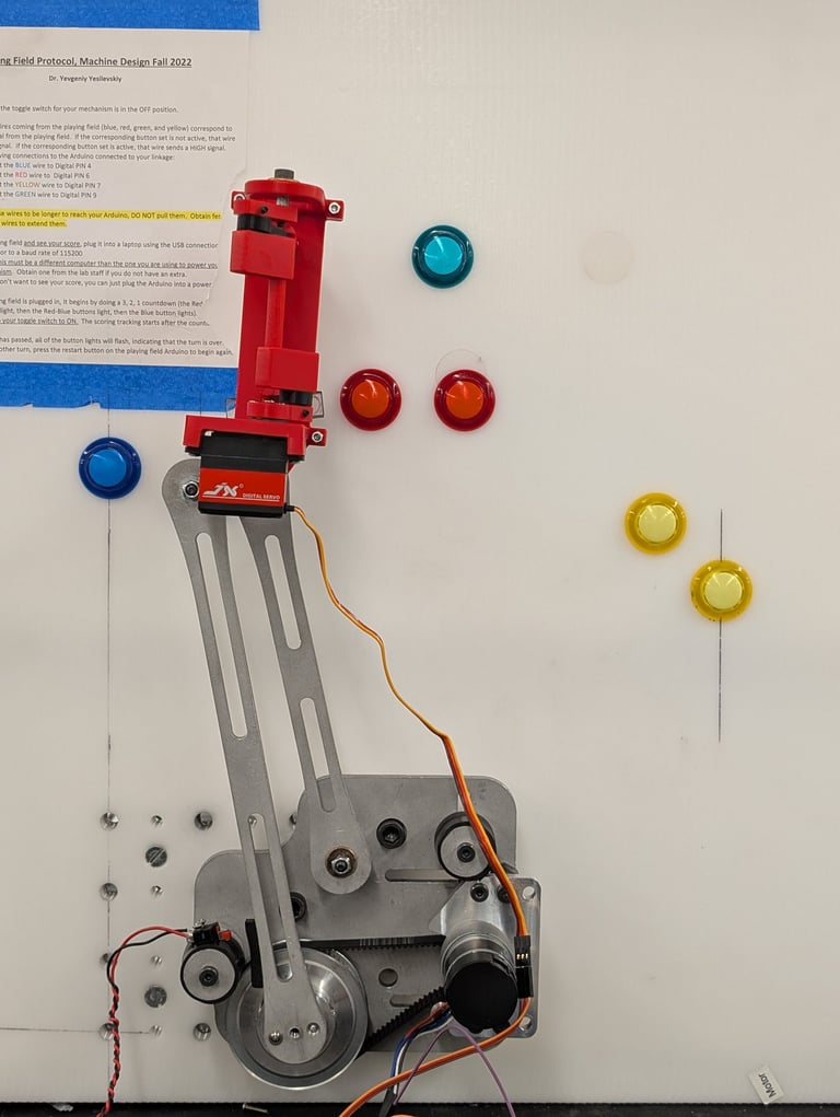
Final Assembly
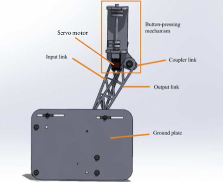
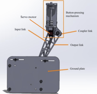
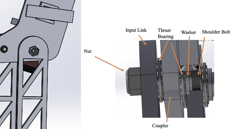
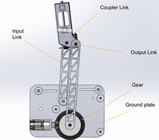
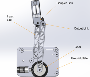
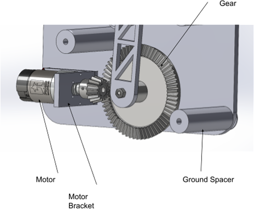
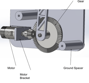
Initial CAD Assembly with labeled components (front view)
Initial CAD Assembly with labeled components (front view)

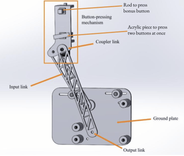
Button-Pressing Mechanism
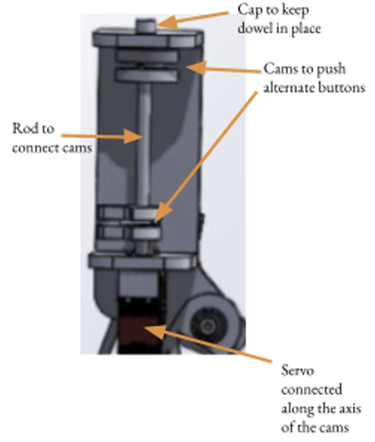
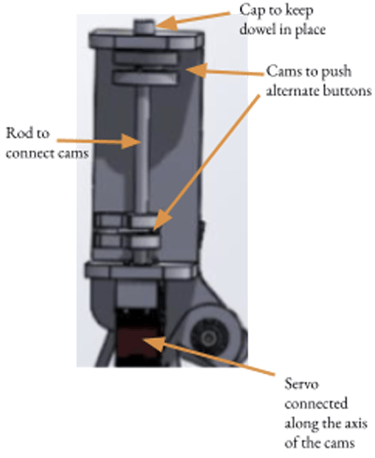

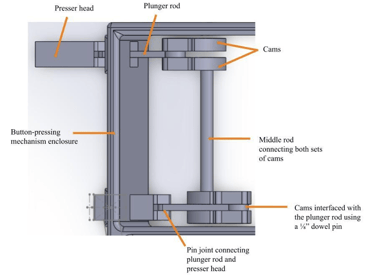
A servo motor powered our button-pressing mechanism which consists of two sets of cams each connected to a button presser, which will alternate pressing buttons depending on the angle of rotation of the servo motor.
The button pressers are composed of a plunger rod which on one end rotates with the set of cams, and on the other contains a pin joint which connects it to the presser head.
The 2” x 0.5” acrylic piece will connect to the bottom button presser, which is aligned to the three pairs of buttons, while the top presser head will solely push the bonus button.
Linkage Joints
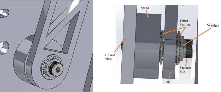
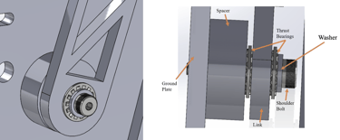
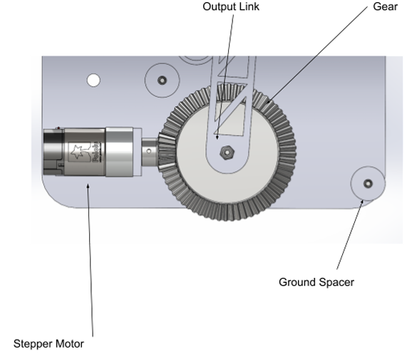
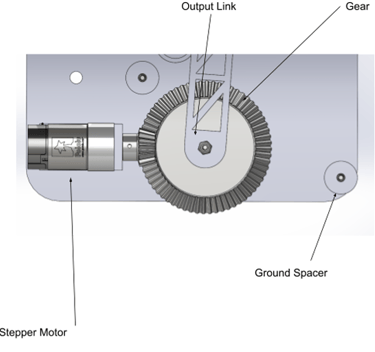
Output Link Joint View and Side View
The shoulder bolt is screwed into the ground plate. The bolt head interfaces with a washer, then a thrust bearing.
Next, is the output link, which contacts the second thrust bearing, and this is separated from the ground plate with a spacer. All links contain a sleeve bearing that rotates around the shoulder bolt.
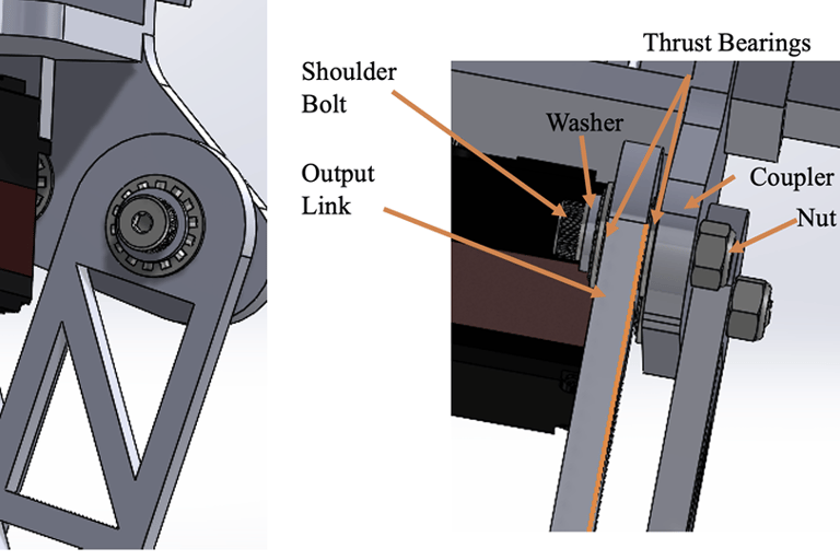
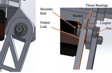
The shoulder bolt interfaces with a washer and then a thrust bearing. The thrust bearings contact the output link. The nut is screwed onto the bolt, securing the joint.
Coupler and Output Link Joint
Ground Plate Assembly
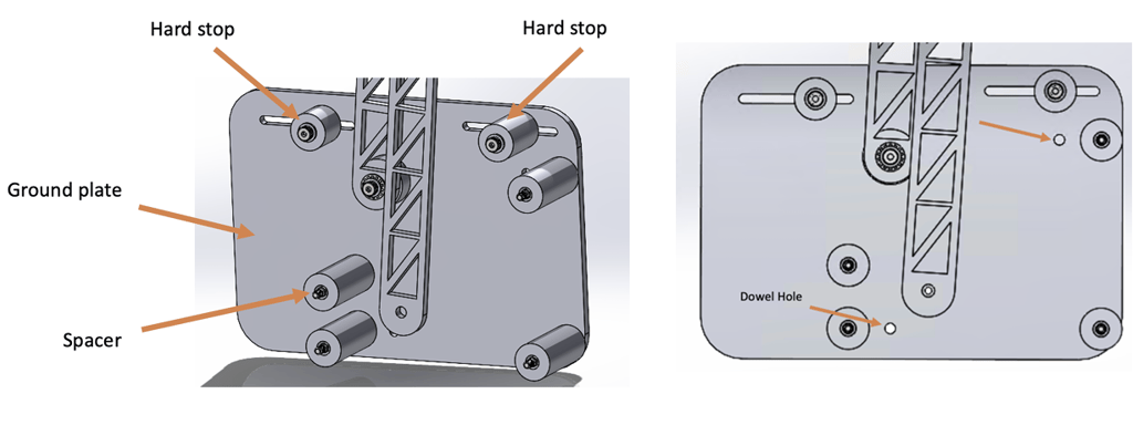
The ground plate is attached to the board at a distance, with the four spacers. Dowel holes will be used for alignment of the plate to the board.
The spacers are fixed by shoulder bolts. The hard stops are fit in slots so that they can be adjusted. There is a gap between the input link and the ground plate for room for transmission.
Project Overview
Project Deep Dive

Full Assembly with Transmission
(initial design before switching to belt drive)
From inertia matching of our linkage at each of its three positions, we calculated a transmission ratio of 3.175. We also calculated the minimum transmission ratio based on a 0.5mm position resolution of the button-pressing mechanism and found it to be 1.806. Our calculated transmission ratio from inertia matching is the most conservative value, however we ultimately decided to go with an even more conservative transmission ratio of 4.
Our input and follower links are relatively long (12.11” and 9.08” respectively), so to ensure our linkage moves smoothly without getting stuck in any extreme positions, we decided a higher transmission ratio would be ideal.
Our transmission system consists of a beveled gear and a pinion in a 4:1 ratio: the beveled gear has 64 teeth and the pinion has 16 teeth. The pinion is directly connected to the motor shaft and meshes with the beveled gear which is sandwiched between the input link and the ground plate. The beveled gears and pinions we found commercially available online were outside of our budget so we’ve decided to try to print our parts out of ABS.
A Bad Setback...
During one of our last build sessions before the final performance review, our belt drive system snapped.
We were under real pressure to finish, and because of different final exam schedules my teammates weren’t available, so I had to figure out a fix for the transmission.
I took to SOLIDWORKS and modeled a new shaft adapter that would let us mount a different gear and run a new belt. That change also required a new motor mount, so I designed that too.
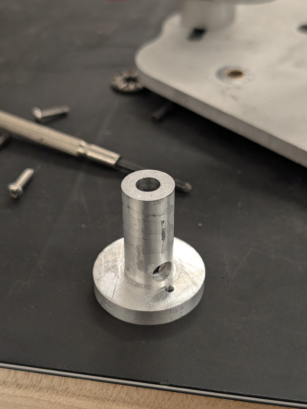
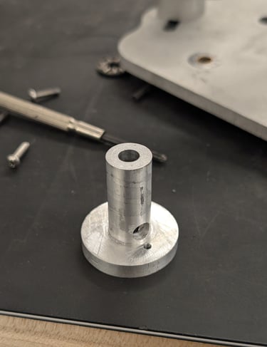
Using my superuser privileges and machining experience, I machined the shaft on the CNC mill and lathe and got it all done in under three hours. We reassembled, tensioned the new belt, and the transmission was functioning perfectly!
That fix saved the project and we competed with a drivetrain that worked.
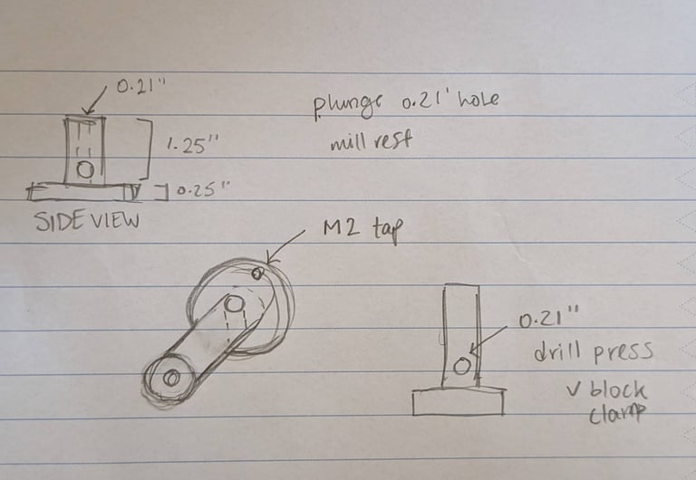
I disassembled the transmission, sketched a few quick ideas on paper, and talked through them with the team.
We agreed to take the risk of a permanent change.
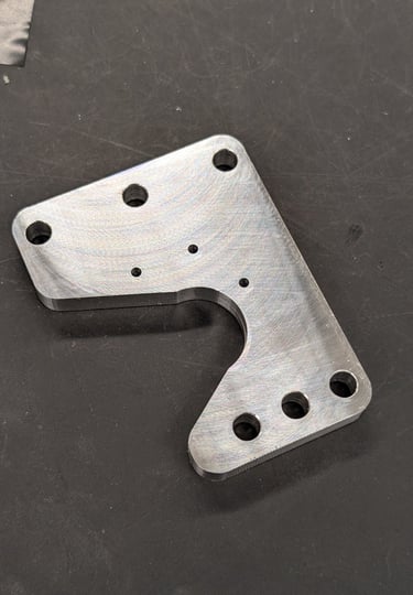
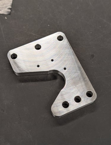
Custom Shaft Adapter
New Motor Mount
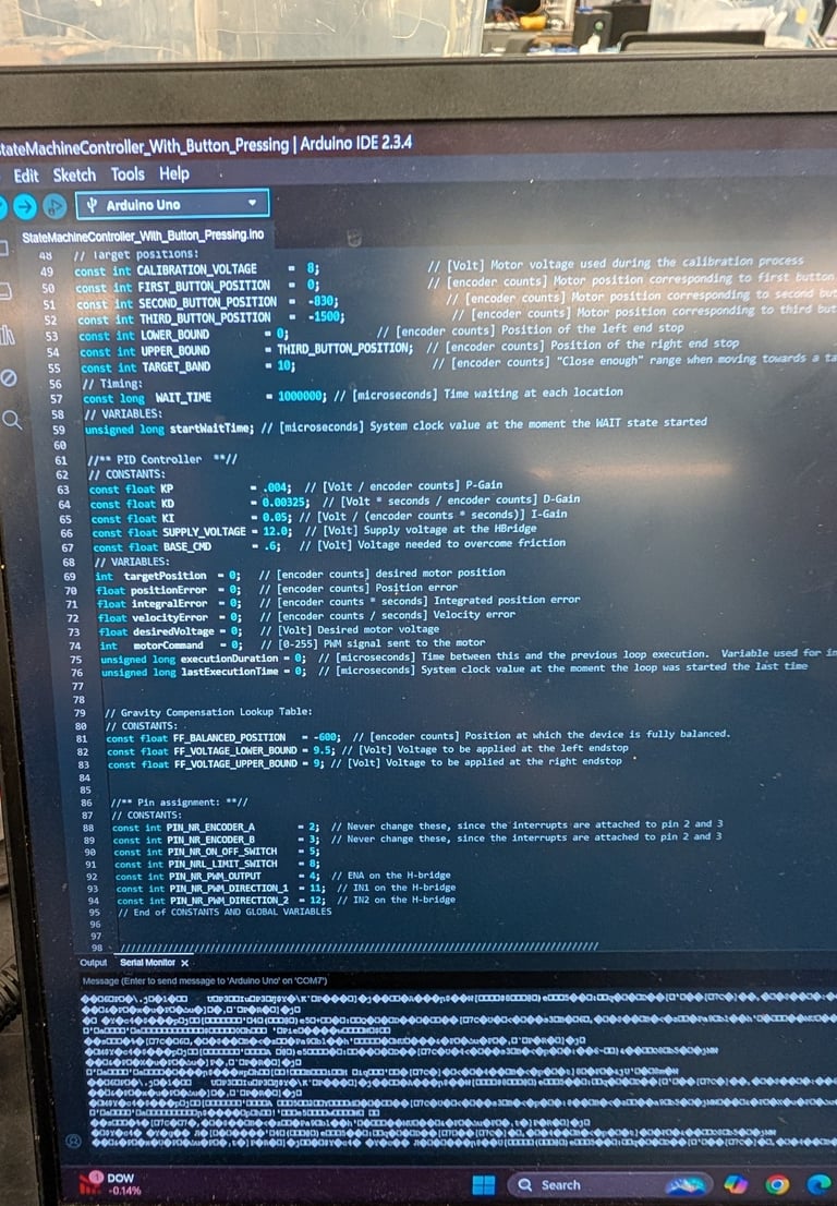
Code + Controls
We ran a closed-loop position control system. An Arduino read the arm’s position from the motor's encoder through an H-bridge with PWM. Because we used external power and had a moving linkage, we took basic safety precautions while testing.
Implementation notes we used:
Clamp the controller output to the safe PWM range, and pause the integral term when the output is saturated (simple anti-windup). That kept behavior stable across different loads.
Basic Hardware used: Arduino, position sensor (encoder/pot), L298N-style H-bridge, 12 V supply.
PID Tuning
Our goal was simple: get the arm to the target fast, stop on target, and avoid big overshoot.
To do that, we tuned the three PID gains:
Kp (proportional): pushes based on how far you are from the target.
Kd (derivative): adds braking based on how fast you’re moving.
Ki (integral): cleans up small leftover error (bias/friction).
How we tuned it (and what worked):
P-only pass. Start small and raise Kp until the arm just begins to oscillate around the target, then back off a bit.
→ We landed around Kp = 1.6 (error in degrees, loop ~100 Hz, PWM 0–255).Add D to calm overshoot. Increase Kd until the wobble settles quickly without feeling sluggish.
→ Kd = 0.10 gave a quick stop with minimal ringing.Add a little I to remove bias. Bring Ki up just enough to kill steady-state error, but keep it small to avoid windup.
→ Ki = 0.02 cleared residual error without hunting.